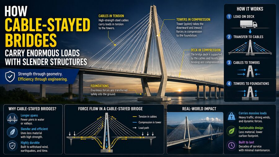

Cable-stayed bridges are among the most visually striking structures in modern civil engineering. Their tall towers, fan-like cables, and thin road decks can make them appear almost delicate, yet these bridges are capable of carrying thousands of vehicles, heavy trucks, wind loads, and their own enormous weight across wide rivers, valleys, and shipping channels. 🚗🚛🌊
The reason they can remain so slender while supporting such large loads lies in the way forces are redirected through the structure.
Instead of relying on a massive solid beam to span the entire distance, a cable-stayed bridge uses a carefully arranged system of deck, cables, towers, and foundations. The deck carries traffic, the cables pull upward on the deck, the towers carry large compressive forces downward, and the foundations transfer those forces into the ground.
This creates a highly efficient load path.
In simplified form:
Vehicle load ➡️ Bridge deck ➡️ Stay cables ➡️ Towers ➡️ Foundations ➡️ Ground
By placing each structural element primarily in the type of loading it handles best, engineers can build bridges that are both strong and remarkably slender. 🧠⚙️
🌉 What Is a Cable-Stayed Bridge?
A cable-stayed bridge is a bridge in which the main deck is directly supported by inclined cables connected to one or more towers.
These inclined cables are called stay cables.
Unlike a suspension bridge, which uses a large curved main cable draped over towers, a cable-stayed bridge connects the deck directly to the towers through many separate stays.
A simplified arrangement looks like this:
        Tower
         │
      \  │  /
       \ │ /
--------\│/--------
        Deck
Each cable supports part of the deck.
Together, they create a structural system capable of spanning long distances without requiring huge numbers of piers in the water below.
🧱 The Main Structural Components
A cable-stayed bridge usually consists of several major elements:
- Deck – carries vehicles, trains, pedestrians, and utilities.
- Stay cables – support the deck and transfer forces to the towers.
- Towers or pylons – receive cable forces and carry them downward.
- Anchorages – securely connect the cables to the deck and towers.
- Piers and foundations – transfer forces into the ground or riverbed.
Each component has a specialized structural role.
The bridge works efficiently because these components cooperate instead of one member carrying the entire burden.
🚗 What Happens When a Truck Drives Onto the Bridge?
Imagine a heavy truck driving onto the center of a cable-stayed bridge.
Its weight pushes downward on the deck.
If the bridge were simply a long unsupported beam, the deck would need to be extremely deep and heavy to resist bending.
Cable-stayed bridges solve this differently.
Nearby stay cables pull upward on the deck.
The force travels:
Truck weight ➡️ Deck ➡️ Cable tension ➡️ Tower compression ➡️ Foundation
This significantly reduces the bending demand in the deck.
Instead of acting as one giant unsupported beam, the deck behaves more like a series of shorter spans supported at many cable attachment points.
That is one major reason the deck can remain relatively thin. ✨
🪢 Why Cables Are So Efficient
Steel cables are extremely effective structural elements because steel performs very well in tension.
Tension means a member is being pulled apart.
A stay cable is always designed primarily to resist pulling force.
When the deck tries to sag under weight, the cable becomes tensioned and pulls upward.
Because cables do not need to resist much bending, engineers can use relatively small cross-sections compared with large beam structures.
Modern stay cables are often made from bundles of high-strength steel strands.
These strands can carry enormous tensile forces while remaining slender.
That combination of:
High tensile strength + low structural weight
makes cables ideal for long-span bridges. 🪢💪
🗼 Towers Carry Compression
While the cables experience tension, the towers mainly experience compression.
Compression means a member is being pushed or squeezed.
Every cable pulling on the tower contributes a force.
The horizontal components of cable forces tend to balance between opposite sides of the tower, while the vertical components combine and push downward.
The tower then transfers this compression into its foundation.
Conceptually:
Cable tension ➡️ Tower compression ➡️ Foundation reaction
Concrete and structural steel are both very effective at carrying compressive forces when designed properly.
This allows the towers to remain tall and relatively narrow.
📐 How Angled Cables Support the Deck
A stay cable does not pull straight upward.
It is installed at an angle.
Therefore, cable tension contains two force components:
- A vertical component
- A horizontal component
The vertical component supports the deck’s weight.
The horizontal component pulls the deck toward the tower.
The deck must therefore resist some axial compression or tension as part of the overall structural system.
Engineers carefully balance these forces so the deck, towers, and cables work together.
The cable angle matters greatly.
A cable that is too shallow must carry much higher tension to provide the same vertical lifting force.
Steeper cables are structurally more efficient but require taller towers.
Bridge design therefore involves a compromise between tower height, cable forces, deck geometry, and construction cost. 📏
🧮 How Loads Are Shared Between Many Cables
A cable-stayed bridge uses many cables instead of only one or two.
Each stay typically supports a particular region of the deck.
This distributes the bridge load over many structural paths.
If one section experiences heavier traffic, the nearby cables take more load while the deck redistributes some of the force to adjacent stays.
This distribution improves efficiency.
Instead of requiring one enormous structural member to carry everything, the total load is shared among many smaller members.
This is similar to how many spokes support the rim of a bicycle wheel. 🚲
🌟 Fan, Harp, and Semi-Fan Cable Arrangements
Stay cables can be arranged in several patterns.
🪭 Fan Arrangement
In a fan arrangement, many cables meet near the top of the tower.
This creates steep cable angles and can be structurally efficient.
🎼 Harp Arrangement
In a harp arrangement, the cables remain nearly parallel and connect to different heights along the tower.
This creates a visually regular appearance.
🌉 Semi-Fan Arrangement
A semi-fan configuration spreads the cable anchor points near the upper part of the tower rather than connecting them all at one exact location.
Many modern bridges use this compromise because it combines structural efficiency with practical construction and maintenance.
🧱 Why the Deck Can Be So Thin
Traditional beam bridges resist loads largely through bending.
Bending causes the top of a beam to compress while the bottom stretches in tension.
For very long spans, bending forces can become extremely large.
A cable-stayed bridge reduces this problem because the deck receives vertical support at frequent intervals from the cables.
The effective unsupported length between support points is much smaller.
This means the deck does not need to be as massive as a conventional long-span girder.
The deck still needs enough stiffness to resist:
- Local bending
- Traffic loads
- Wind
- Torsion
- Cable-force imbalances
But it can often remain much shallower than a purely beam-supported structure.
This creates the elegant, slender appearance associated with cable-stayed bridges. 🌉✨
↪️ How the Deck Handles Compression
Because inclined stay cables pull inward toward the towers, they create horizontal forces in the deck.
These forces can place large portions of the deck under compression.
This is actually beneficial when the deck is designed for it.
Rather than resisting all loads through bending alone, the deck can carry part of the load through axial force.
Structural systems are often more efficient when loads are carried as direct tension or compression rather than bending.
That principle is one of the reasons cable-stayed bridges can be so lightweight relative to their span.
🌬️ How Bridges Resist Wind
Long-span bridges must resist enormous wind forces.
Wind can push sideways on the deck, towers, vehicles, and cables.
It can also create oscillations.
Engineers therefore use aerodynamic analysis to shape the bridge deck.
A streamlined deck reduces turbulence and unwanted vibration.
Wind-tunnel testing may be used to study:
- Flutter
- Vortex shedding
- Buffeting
- Cable vibration
Flutter is especially dangerous because aerodynamic forces can interact with structural motion and create growing oscillations.
Modern cable-stayed bridges are carefully designed to avoid these unstable behaviors. 🌬️
🪢 Cable Vibration and Dampers
Stay cables are long, flexible members and can vibrate under certain conditions.
Possible causes include:
- Wind
- Rain
- Traffic-induced vibration
- Motion of the bridge deck
One phenomenon is called rain-wind-induced vibration, in which water and airflow interact around the cable surface.
Engineers may install:
- Dampers
- Surface treatments
- Cross-ties
- Aerodynamic cable sheathing
These devices reduce vibration and help prevent fatigue damage over many years.
🚛 Moving Traffic Creates Dynamic Loads
Vehicles do not apply perfectly static loads.
A heavy truck driving over bumps creates changing forces.
Trains can also produce repeated dynamic loading.
The bridge must therefore withstand not only the weight of traffic but also vibrations caused by movement.
Engineers analyze:
- Traffic patterns
- Vehicle speeds
- Dynamic amplification
- Fatigue cycles
- Resonance risks
Because bridges are expected to survive millions of vehicle crossings, fatigue is a major design concern.
🔄 What Happens When Loads Are Uneven?
Imagine heavy traffic building up on one side of the bridge while the opposite side remains relatively empty.
The bridge experiences an unbalanced load.
The deck may try to twist or deflect asymmetrically.
The stay cables on one side may carry different forces from those on the other.
The towers can also bend slightly.
Engineers design the system so all components remain within allowable stress and deformation limits under these uneven conditions.
Computer models can simulate thousands of different loading combinations.
🌡️ Temperature Causes Bridges to Expand and Contract
Bridges are exposed to large temperature changes.
Steel and concrete expand when heated and contract when cooled.
Across a long bridge, even a small amount of thermal expansion per meter can produce significant total movement.
Cable-stayed bridges therefore include components such as:
- Expansion joints
- Bearings
- Flexible details
These allow the structure to move without generating damaging internal forces.
Cable lengths and tensions also change slightly with temperature, so engineers account for thermal effects during design.
🌊 Foundations Carry Everything Into the Ground
Ultimately, every load on the bridge must reach the ground.
The towers can carry enormous vertical forces.
If a bridge crosses deep water or weak soil, foundations may extend far below the surface.
Possible foundation systems include:
- Large reinforced-concrete footings
- Driven piles
- Drilled shafts
- Caissons
Engineers perform geotechnical investigations to determine whether the soil or rock can safely carry these forces.
If the foundation moves excessively, the entire bridge geometry can be affected.
⚖️ Structural Balance Is Essential
Cable-stayed bridges are carefully balanced systems.
During normal operation, cable forces on opposite sides of a tower help balance each other.
If a cable on one side pulls strongly while the opposite side has insufficient balancing force, the tower may experience large bending moments.
This balance is especially important during construction.
Engineers often build outward from the tower in nearly symmetrical segments.
A deck section is installed on one side.
Then a corresponding section is installed on the other.
New stay cables are tensioned as construction progresses.
This balanced cantilever method prevents excessive temporary forces in the tower. 🏗️
🏗️ How Cable-Stayed Bridges Are Constructed
One major advantage of cable-stayed bridges is that they can often be built without extensive temporary supports beneath the span.
This is useful over:
- Deep rivers
- Busy shipping lanes
- Wide valleys
Construction may proceed outward from the tower.
A typical sequence is:
Build tower ➡️ Install deck segment ➡️ Attach stay cable ➡️ Add next segment ➡️ Add next cable
The bridge gradually extends farther into space while the cables support each new segment.
Eventually, the sections meet near the center.
This method makes cable-stayed bridges particularly attractive where building temporary scaffolding would be difficult or impossible.
🎯 Cable Tension Must Be Carefully Controlled
Each stay cable must be tensioned to a specific force.
Too little tension may allow the deck to sag.
Too much tension may overload the deck or tower.
During construction, engineers repeatedly measure and adjust cable forces.
Techniques may include:
- Hydraulic jacks
- Strain measurements
- Vibration-frequency measurements
- Laser surveying
Cable force is often monitored throughout the bridge’s life.
📡 Structural Health Monitoring
Modern cable-stayed bridges may contain extensive sensor systems.
Sensors can measure:
- Cable tension
- Deck vibration
- Tower movement
- Wind speed
- Temperature
- Strain
- Traffic loads
Data can be continuously collected and analyzed.
If unusual behavior appears, engineers can investigate before serious damage develops.
This is known as structural health monitoring. 📊
🧮 Computer Modeling Makes Slender Designs Possible
Modern cable-stayed bridges rely heavily on computer analysis.
Engineers create detailed finite-element models of:
- Towers
- Cables
- Deck
- Foundations
The computer calculates how the bridge responds to thousands of possible situations.
These may include:
- Heavy traffic
- Extreme wind
- Earthquakes
- Cable failure
- Temperature changes
- Construction stages
This allows engineers to optimize the structure so material is placed only where necessary.
Without advanced numerical modeling, designing extremely slender modern bridges would be much more difficult.
🌎 Earthquake Resistance
In earthquake-prone regions, cable-stayed bridges must also survive severe ground movement.
Earthquakes can cause towers and foundations to move while the deck has significant inertia.
Engineers may use:
- Seismic bearings
- Dampers
- Flexible connections
- Reinforced tower designs
- Foundation strengthening
Computer simulations predict how the entire bridge responds to different earthquake motions.
The objective is not always to prevent every movement, but to control forces and prevent catastrophic failure.
🔐 What If One Stay Cable Is Damaged?
Modern bridge design often includes redundancy.
If one cable is damaged or temporarily removed for maintenance, the bridge should ideally be able to redistribute the load to neighboring structural elements without sudden collapse.
Engineers may perform cable-loss analyses to study these conditions.
Replacement procedures can then be planned.
Because stay cables are exposed structural components, they are usually designed so individual cables can be inspected and replaced if necessary.
🌁 Cable-Stayed vs. Suspension Bridges
Cable-stayed and suspension bridges may look similar, but their structural systems are different.
A suspension bridge uses:
Deck ➡️ Vertical hangers ➡️ Main cable ➡️ Towers and anchorages
A cable-stayed bridge uses:
Deck ➡️ Inclined stay cables ➡️ Towers
Cable-stayed bridges do not usually require the enormous end anchorages needed by classic suspension bridges.
For medium-to-long spans, this can make them highly economical.
Suspension bridges remain especially effective for the very longest spans, while cable-stayed bridges occupy a broad and highly competitive span range.
💰 Why Engineers Choose Cable-Stayed Designs
Cable-stayed bridges offer several advantages:
- Efficient structural behavior
- Long spans
- Fewer piers in waterways
- Relatively slender decks
- Efficient construction methods
- Strong visual identity
- Reduced need for massive anchor blocks
They are especially attractive when a crossing must keep navigation channels open.
However, they also require careful cable maintenance, sophisticated analysis, and precise construction.
🧠 The Structural Principle Behind Their Strength
The elegance of a cable-stayed bridge comes from directing forces efficiently.
Instead of forcing a massive beam to bend across a huge gap, the structure converts much of the load into:
Tension in the stay cables
and:
Compression in the towers and deck
Tension and compression can be carried very efficiently by modern high-strength materials.
This makes it possible to achieve a large span with comparatively little structural material.
The bridge looks slender because its strength comes from geometry and force distribution, not simply from mass.
🌟 The Bigger Picture
Cable-stayed bridges are powerful examples of how engineers use structural mechanics to achieve both strength and elegance.
When traffic pushes downward on the deck, the deck transfers much of that force into the stay cables.
The cables carry the force as tension.
The towers receive those cable forces and carry them primarily in compression.
The foundations then transfer the resulting loads into the ground.
The complete load path is:
Traffic 🚗 ➡️ Deck 🌉 ➡️ Stay cables 🪢 ➡️ Towers 🗼 ➡️ Foundations 🧱 ➡️ Ground 🌍
Because the deck receives frequent support from the stay cables, it does not need to behave like one enormous unsupported beam.
That allows engineers to use thinner, lighter deck sections while still crossing impressive distances.
Advanced materials, aerodynamic design, precise cable tensioning, computer simulation, and structural monitoring make these designs even more efficient and reliable.
The result is a bridge that may look almost impossibly delicate from a distance, yet is capable of carrying enormous loads every day.
Cable-stayed bridges demonstrate a fundamental principle of engineering: a structure does not need to be massive to be strong if its forces are directed along efficient load paths. 🌉⚙️✨